Lab 3
Prelab
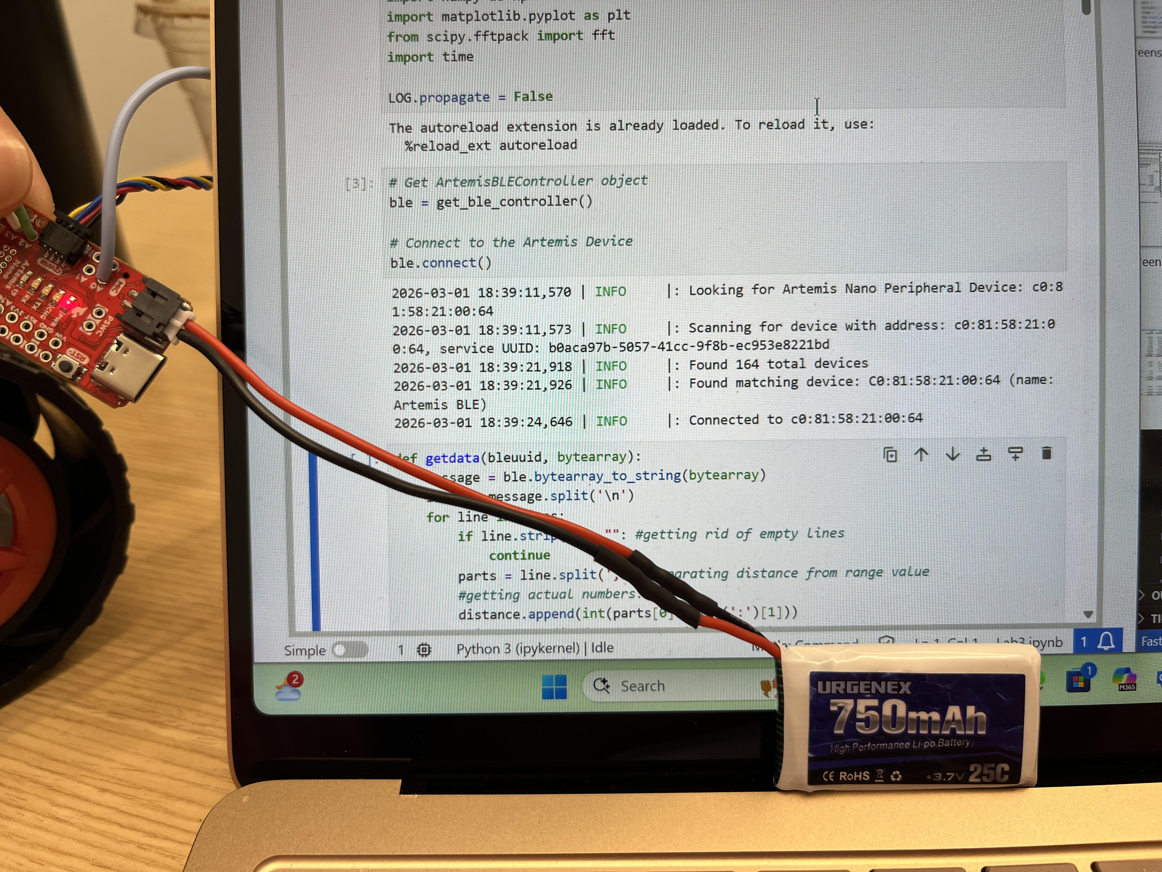
In this lab we begin to work with the two Time of Flight sensors that will be in our car. I began by soldering the connections to the Artemis itself, making sure I take into account the final wiring and components that the car will have, and finally integrating the two sensors along with the IMU to send data via BLE.
I began the lab by soldering both Time of Flight sensors with the configuration shown below. The sensor below is the one I decided to solder the XSHUT pin to Artemis pin A0. I did this in order to later change the I2C address of one of the sensors.
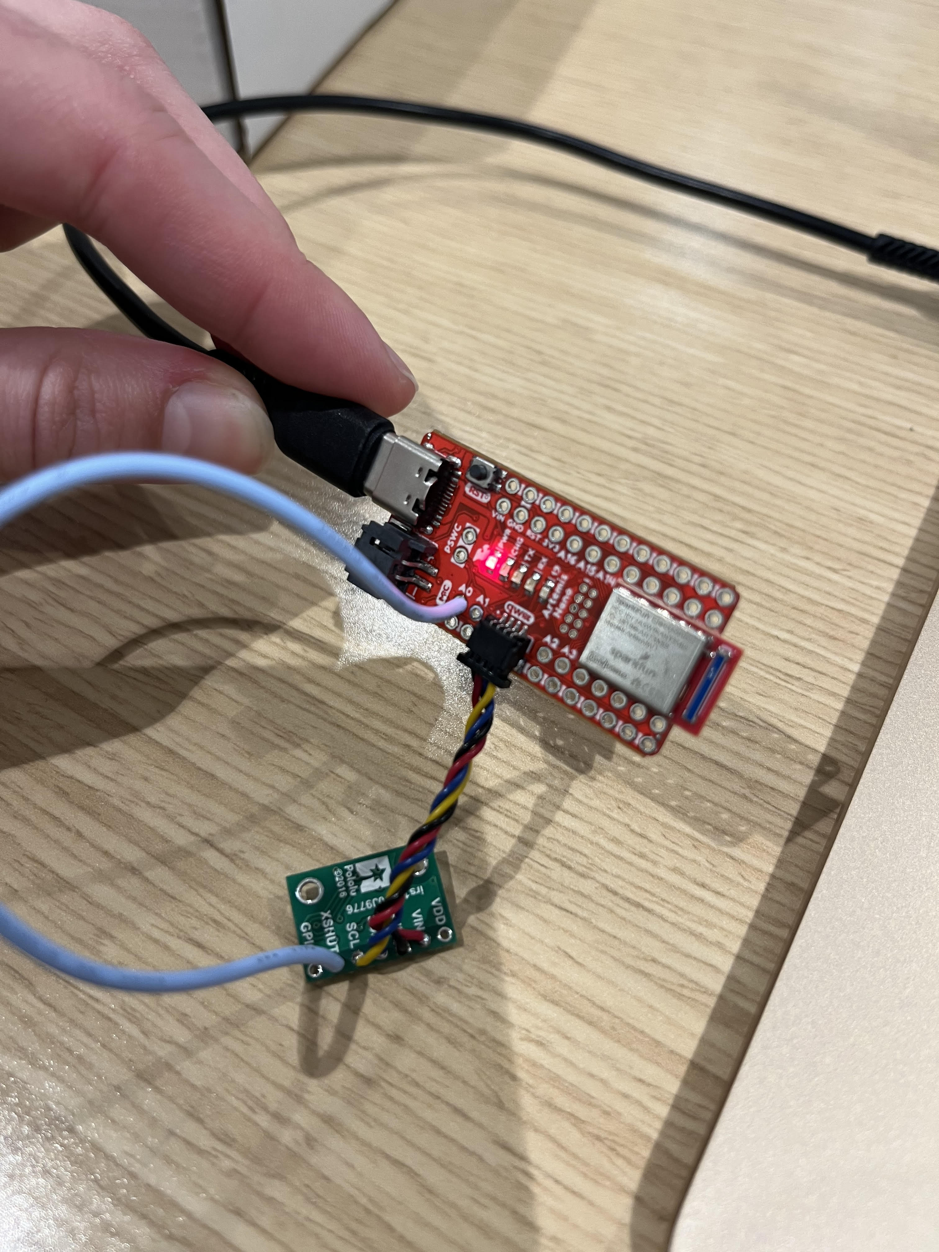
Once wired to the Artemis I ran the Example05_wire_I2C example and received the following output:
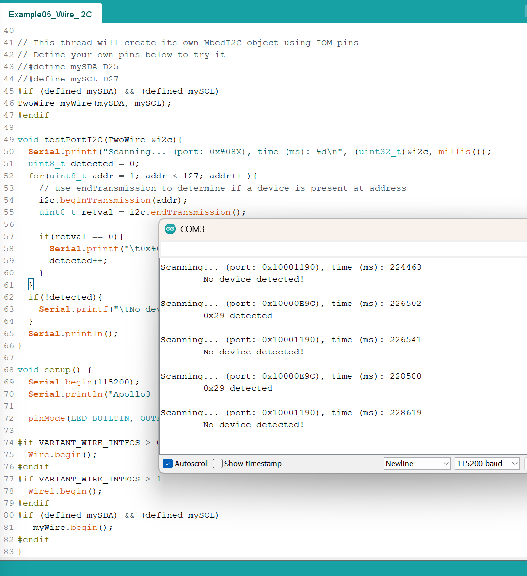
The default I2C address for both ToF sensors is 0x29. In order to connect to and work with both at the same time, I decided to shut off the sensor whose XSHUT pin is connected to the Artemis, and initialize and change the other's I2C address. This way, once I turn on the other sensor, its default address of 0x29 will not clash with the other sensor.
Wiring and Placement
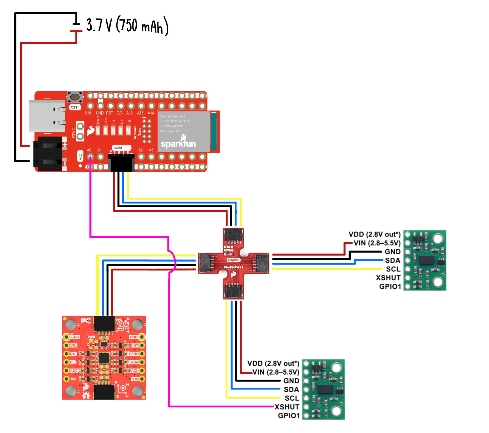
I decided to place one sensor in the front, and another 90 degrees from the front sensor, such that one sensor is on the car's x-axis and the other is on the y-axis. Since each sensor can only read measurements in one direction along one axis, their combined coverage is two narrow cones. This leaves a large blind spot along the diagonals. Therefore, in order to get a complete view of the environment, the car would have to spin or turn a bit. The wire diagram is the following:
Task 1 - Battery Connection
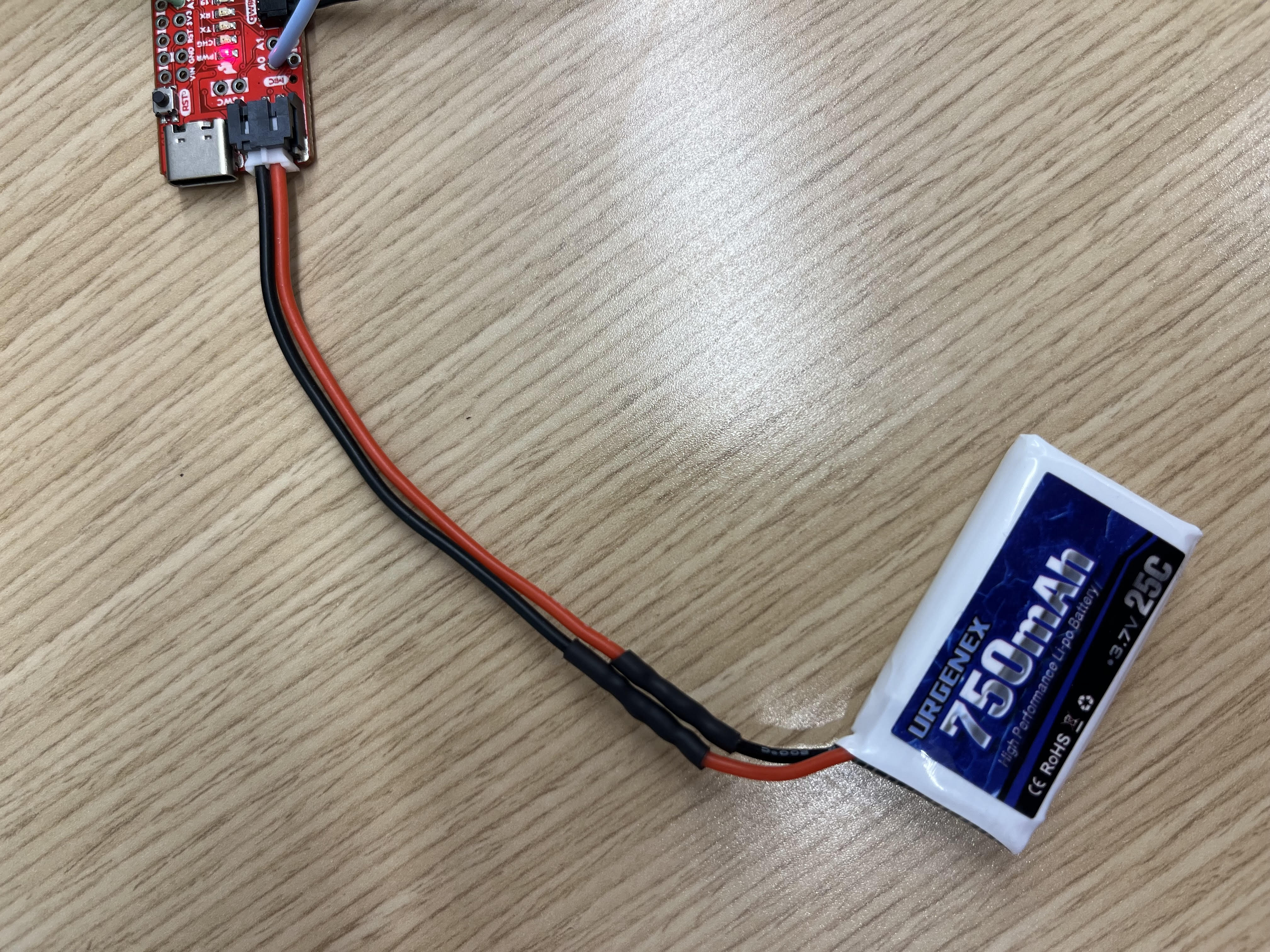
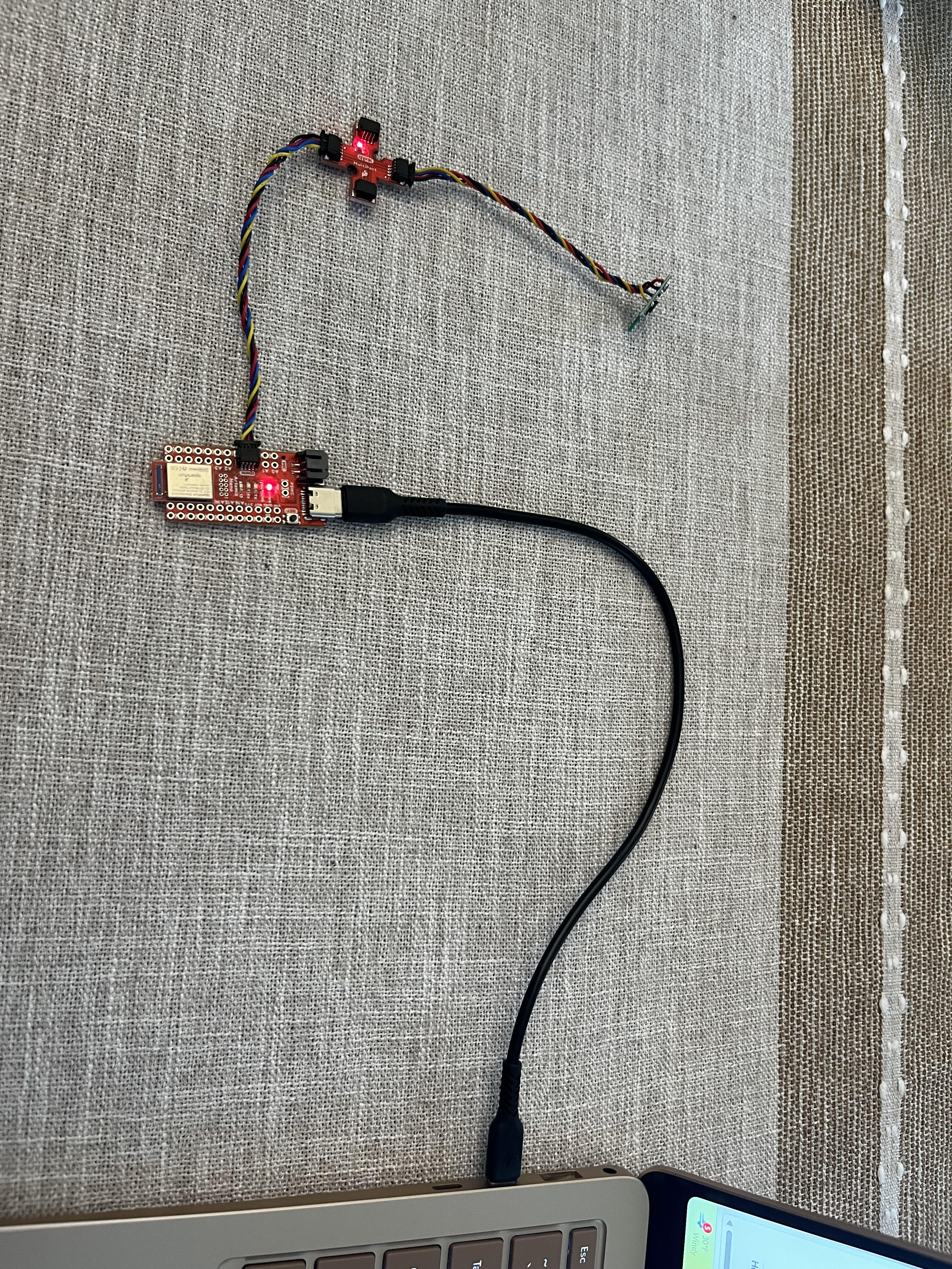
To begin, I soldered a connector to the 750 mAh battery to connect to and power the Artemis. The connector's cable colors do not match up with the polarity of how the connector plugs into the Artemis. Therefore, I had to swap them. I added heat shrink to ensure that there are no shorts between the two wires.
I ran some tests to make sure I could connect and send commands to the Artemis when it is only powered by a battery.
Task 2
I installed the SparkFun VL53L1X 4m laser distance sensor library.
Task 3 & 4 - Connections & Wiring
I connected the first ToF sensor to the Artemis via the QWIIC break-out board.
The wire connections can be seen above and in the prelab section, where I chose the yellow wire to represent the clock signal, the blue wire to represent the data signal, and VIN and Ground are red and black respectively.
Task 6 - Distance Modes
Both ToF sensors have three modes (Short, Medium, and Long), with the Medium mode requiring an additional library. The difference between the short, medium, and long modes have to do with the frequency of the pulses of light that are being shot, and how much time is allocated to wait for the response. The short mode has the fastest sampling rate, making it better suited for short-distances where the light does not have to travel such long distances. The medium and long modes are more sensitive to ambient light, as the time allocated to waiting for the response is greater, allowing it to pick up on more photons that are not necessarily from the sensor’s original pulse of light.
Since our car will be performing high-paced manuevers and operates at quick speeds, I chose the Short mode to be the one that best suits our needs. The following is the output of the ToF sensor at the same distance but at different modes.
Task 7 - Range, Accuracy, and Repeatability
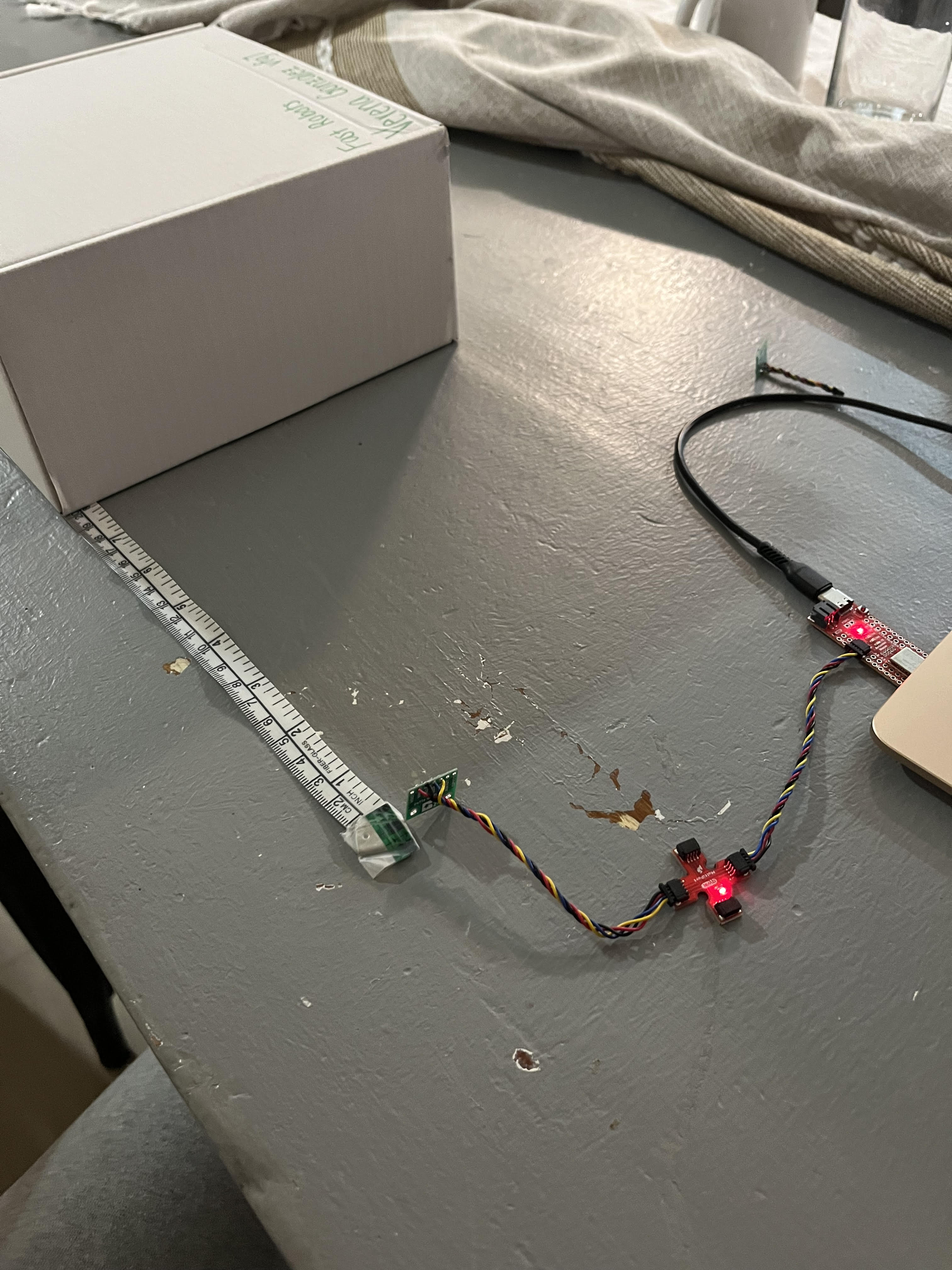
The sensor is rated for a range of 0 - 400cm, however, I noticed that it only started reading values of 0 when the box was held about 20 mm from it. I set up my distance sensor and placed the lab kit box along a tape measure and decided to compare its output to the actual measurement using the set-up below.
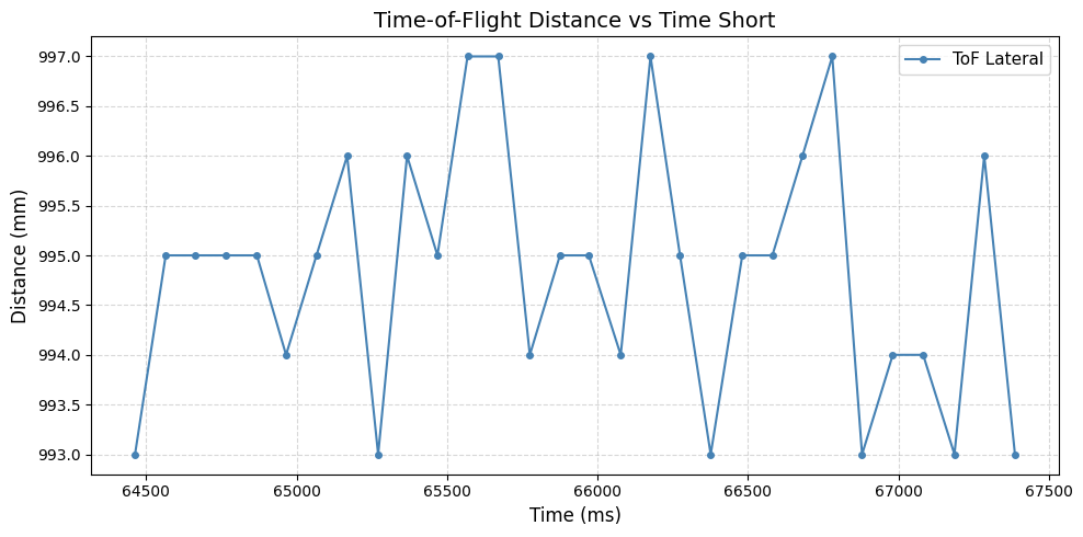
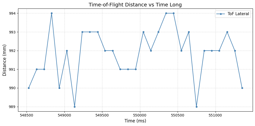
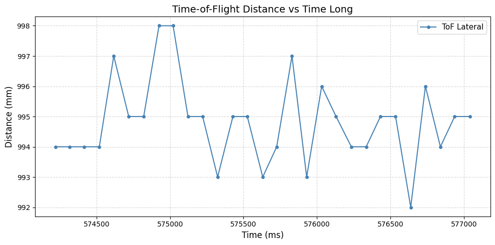
Below are the measurements that I recorded to see how stable the sensor's data was over time.
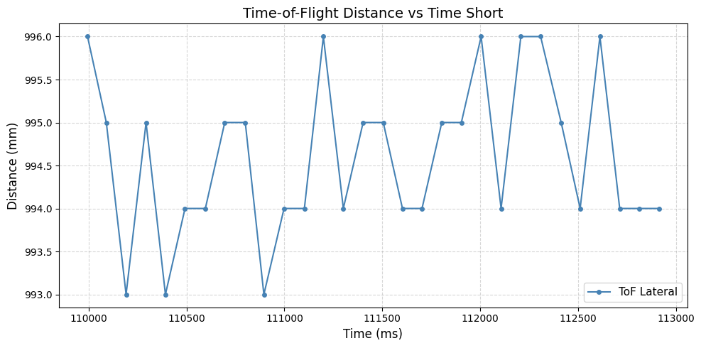
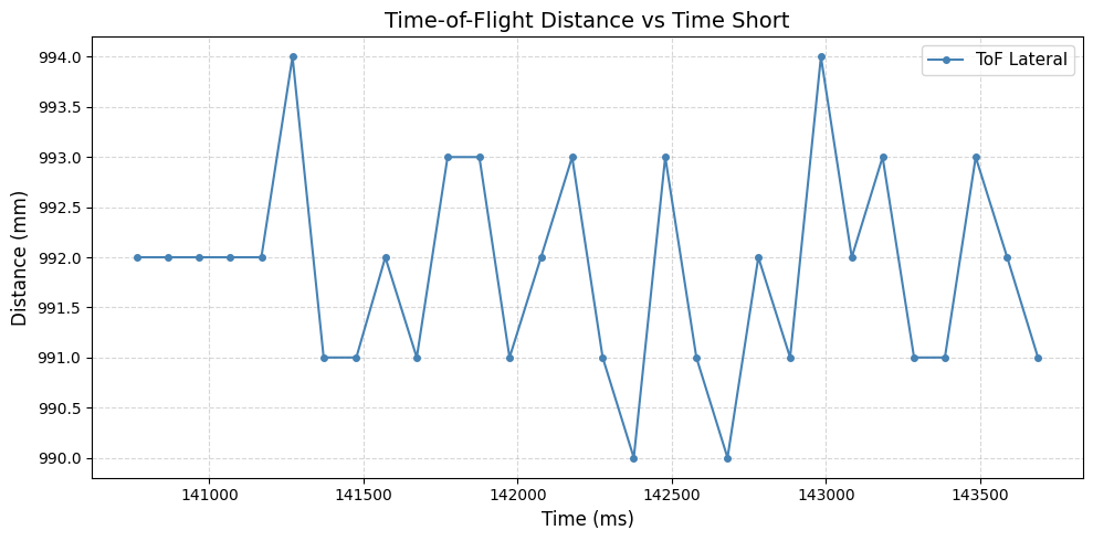
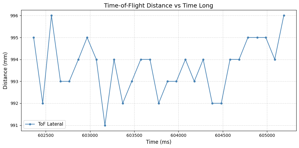
In short mode, the distance measurements ranged rougly between 993 mm and 997 mm, producing a spread of +/- 2mm about the mean. This indicates strong repeatability, with most data points fluctuating only 1-2 mm between successive measurements and the random spikes being attributed to noise.
In long mode, the measurements have a slightly greater variation with a spread of about +/- 3-4 mm about the mean. This makes sense as the sensor increases its measurement timing and signal amplification in this mode which can introduce additional noise.
The actual distance was about 1000 mm, with the Short mode having about 0.5% error, and the long mode having about 0.6% error
Task 8 - Integrating Both ToF Sensors
After having verified that each ToF sensor works, individually, I connected both to the QWIIC breakout board and attempted to receive data from both simultaneously. I managed to do so by following the steps mentioned in the prelab, where I change one of the sensor's I2C addresses while the other is shut off.
Task 9 - Data Speed Collection
Since the car will be constantly running and dependent on each ToF sensor's data, it is important to know how quickly we can collect data. In order to do this I ran the following code that prints the Artemis clock using the millis() function to Serial, along with each ToF sensor's data when available.
if(tof_front.checkForDataReady()){
    int distancef = tof_front.getDistance();
    tof_front.clearInterrupt();
    Serial.print("Front Distance: ");
    Serial.println(distancef);
  }

  if (tof_lat.checkForDataReady()){
    int distancel = tof_lat.getDistance();
    tof_lat.clearInterrupt();
    Serial.print("Lat Distance: ");
    Serial.println(distancel);
  }

  Serial.print("Artemis Clock Time (ms): ");
  Serial.println(millis());
Output: 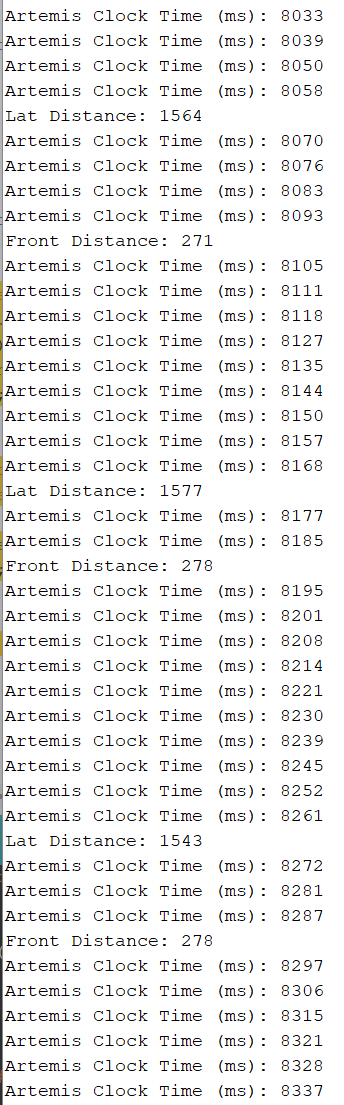
Every "Artemis clock time (ms)" output is printed at the end of the loop, therefore the amount of time between measurements can be estimated by taking the difference between the times when they are printed. For example, the lateral distance is followed by a clock time of 8070, and then is printed out again at 8177. This is a difference of about 100 ms. For the Front distance, similar can be said (8105 → 8195), with a difference of 90 ms. Therefore, both sensors output data at a frequency of about 10 Hz. There is also a delay / phase shift between the two of about 8105 − 8070 = 35 ms, 8195 − 8177 = 18 ms, 8297 - 8272 = 25 ms, averaging to 26 ms. The current limiting factor is how quickly the sensor is able to have new data available. The checkForDataReady function waits until the sensor has adequate data to output, however the sampling frequency itself is pretty consistent. The loop itself takes about 7.84 ms, as seen from the Artemis clock output.
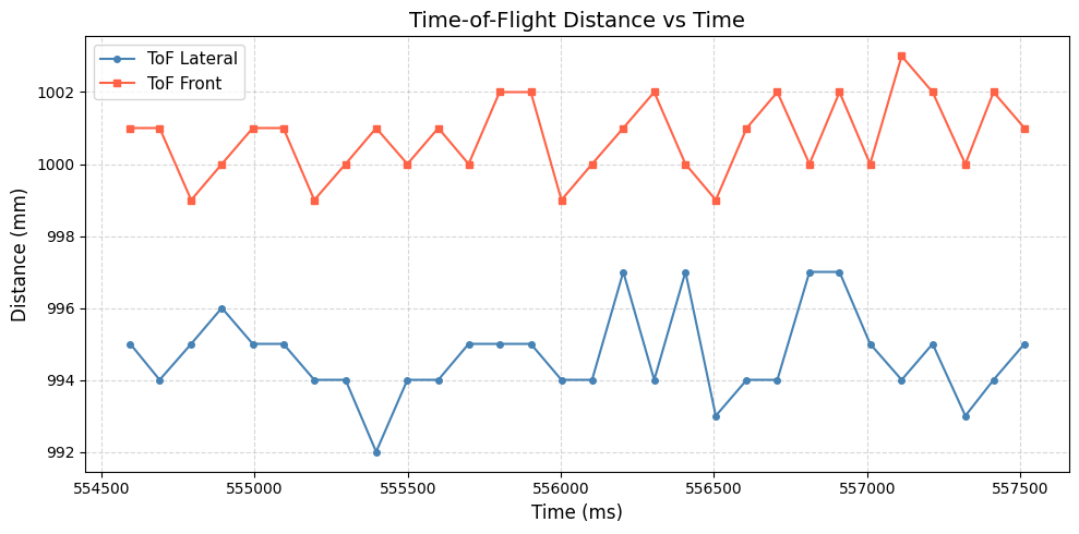
Task 10 - ToF Data vs Time, IMU Data vs Time
Finally, I decided to collect data for approximately 5 seconds at a time and send it over Bluetooth to the computer using this code to collect the data:
while(millis() - startMillis < sampletime){
          recorded = false;
          if(tof_lat.checkForDataReady() && tof_front.checkForDataReady() ){
            toflat_array[samplecount] = tof_lat.getDistance();
            toffront_array[samplecount] = tof_front.getDistance();
            tof_lat.clearInterrupt();
            tof_front.clearInterrupt();
            time_array[samplecount] = millis();
            samplecount++;
          }
      }
I added both checkForDataReady() routine to the if statement, as separating the two as I did previosuly created a phase difference in the sensors' output.
Additional Task 5190
There are many different kinds of distance sensors that are based on infrared transmission with different applications due to their nature. Below are a few that were mentioned in lecture:
Amplitude-based IR sensors have very simple circuitry, and measure the intensity of reflected infrared light (using a photodiode receiver) that was emitted via an IR LED transmitter. They are good for short-ranged (<10cm), fast-paced applications (the simple circuitry has not complex signal or time processing), and do not work well with high ambient light as IR intensity decreases rapidly with distance traveled.
IR triangulation sensors also have simple circuitry and emit focused IR light, however, this sensor measures the angle of the reflection off an object using a position-sensitive detector or CMOS array. These work well in applications < 1m and are not sensitive to surface colors or texture, due to the geometry of the angle change with distance and the fact that it matters more about where the light lands, not the intensity of it.
IR ToF sensors emit pulse-modulated signals and records the time until the signal returns. Because of this, it is mostly insensitive to texture, color and ambient light, and works best in 0.1 - 4m applications.
I decided to test the sensitivity of the ToF sensors when held at the same distance at the wall against white paint, clear plastic, and a black waterproof jacket. The sensor had nearly identical output data for all textures, showing that it was not too sensitive to changes in material and color.
Jacket test: 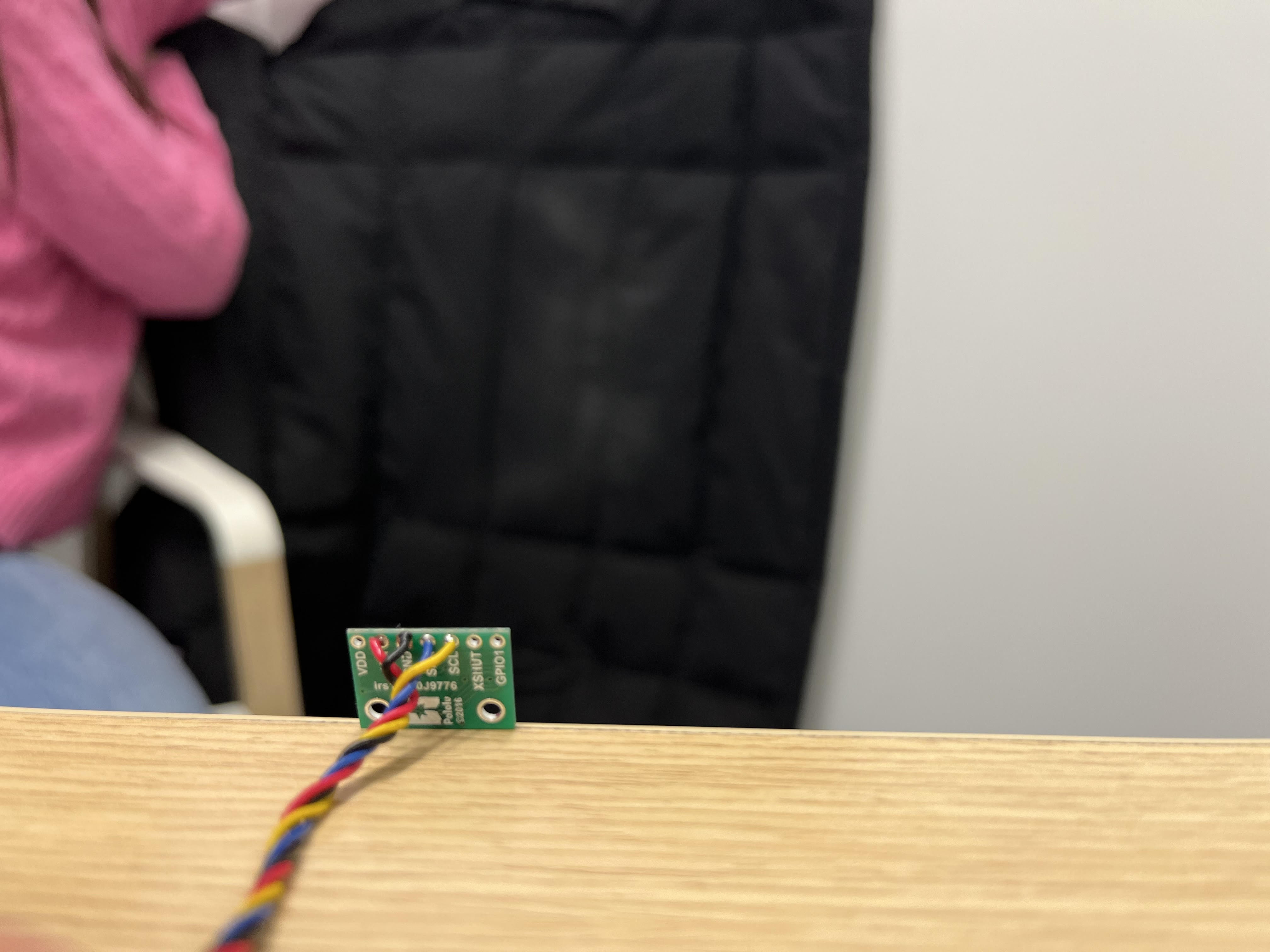
References
I referenced Aidan Derocher's course website from last year as recommended, and worked with the TAs and Farrell in order to debug setting up the addresses for the two distinct ToF sensors.