Lab 4
Prelab
In this lab, we wire up and run tests on our motor drivers. The following diagram shows how I decided to wire all the devices to the Artemis, including the batteries for the motor drivers and the Artemis itself.
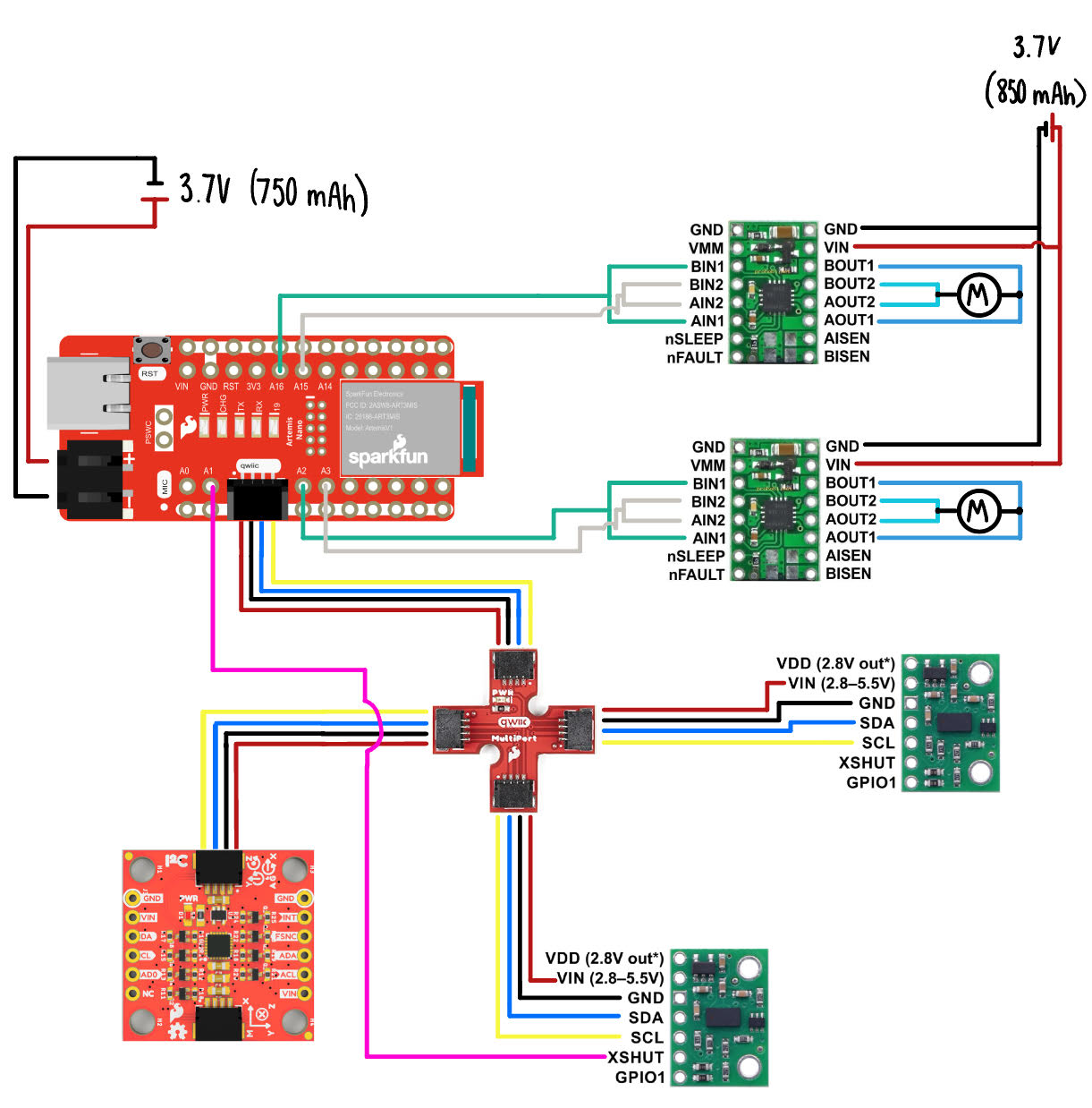
I made sure to choose pins that supported PWM and that made physical sense with regard to the motor drivers' location. The two inputs and outputs are parallel coupled for each motor driver, which is only possible because they are controlled by the same chip running on its own clock circuitry.
As for the wiring, I attempted to cut the wires to lengths that were as short as possible to eliminate EMI, however, long enough to have slack such that connections remain intact. I decided to follow common practice, making sure that wires that supply voltage are red, and all grounding wires are black. The remaining colors I chose personally, and tried to remain consistent. To further reduce EMI between wires and components, I decided to place the Artemis at the far back, away from the motor drivers' battery, twisted wires pairs, and made sure that there were no unintentional wire loops.
The Artemis and the motor drivers are powered by two separate batteries in order to eliminate any possible fluctuations in current supplied, given that the motor drivers pull a lot more current than the Artemis, and may do so sporadically. This can cause voltage spikes, dips, and noise. It is in our best interest to ensure that the Artemis receives stable power given that it controls the motor drivers, all sensors, and overall communication.
Task 1 - Soldering & Setting Up the Motor drivers
I decided to solder the motor drivers as follows, again parallel-coupling the two input and outputs, and grounding the signal to the Artemis.
Before connecting the motor driver to the car, it is important to run some tests, which I did by power the motor drivers to a power supply to be able to control current. The following are general specifications for the motor drivers we're using:
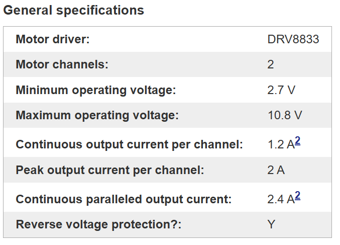
Since the battery that we'll be using provides 3.7V, I set the power supply to just that, and set a current limit of about 2.5A, given that I parallel coupled the two input and outputs.
Task 3 - Generating PWM Signals
To test if the Artemis pins are generating PWM signals, and that they are successfully being transmitted by the motor drivers, I hooked up the motor driver's output for each of its output channels to an oscilloscope and recorded it:
I used the following code to generate the PWM signal, and altered the first argument to select the pin, and the second argument to control the duty cycle:
    void loop(){
        analogWrite(A1_PIN, 128);  // 50% speed
    }
I ran two different duty cycles (50% and 75%) to see the difference in the outputted signal:
Task 4 - Testing the Motors
After having verified the code and signal outputs, I connected each motor driver to the car's actual motors to see if I could turn the wheels forwards and backwards.
Task 5 - Battery-Powered Tests
Now, I decided to run the same tests with the motor drivers being powered by a single 850 mAh battery.
Using this code:
  Right Wheel
  analogWrite(RMD_F, 128); // 50% speed

  //Left Wheel
  analogWrite(LMD_F, 128); // 50% speed
Task 6 - Testing All Motor Drivers
The above tests were run for both motor drivers, ensuring that all connections are properly soldered and wired, and there are no software or hardware issues.
Task 7 - Running the Car
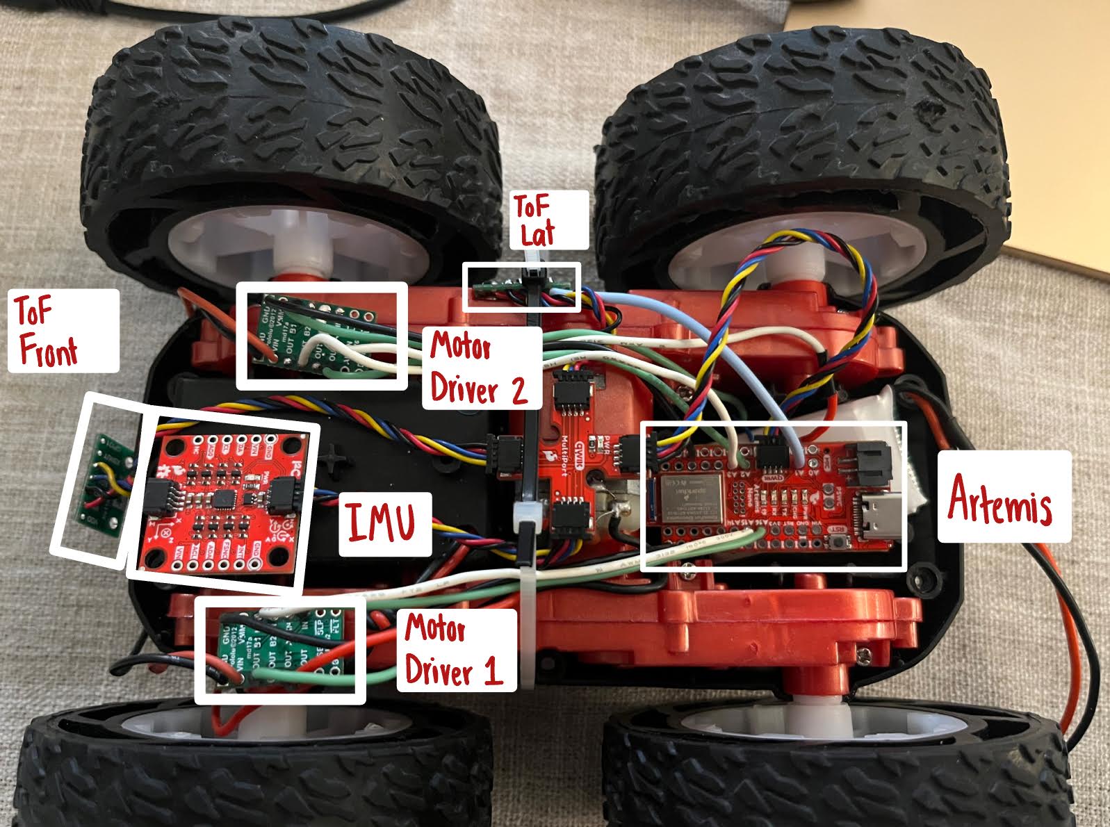
I placed everything onto the car, and starting running it untethered.
Task 8 - Test PWM Limits
In order to test the lower PWM limit for which the robot moves forward and on-axis turns while on the ground I decided to test the lowest value for which it drive forward and on-axis turn while starting from rest.
The lowest PWM value at which the car starts moving from rest is approximately 30. Anything smaller results in the following behavior where the motor cannot overcome the static friction:
The car requires more power to perform an on-axis spin. I found that it required at least ~130 of a PWM signal, if not it will do the following:
Task 9 - Motor Calibration
To see if both of my motors spin at the same rate, I decided to see if my robot could follow a straight line for at least 2m.
Originally it did not:
This led me to empirically find a ratio between what duty cycle I should run one pair of wheels with respect to the other. The wheels on the left required an 80% greater duty cycle than the right-side of wheels. I tested this ratio over a variety of duty cycles to make sure it works with various speeds. Below are two videos of me running the calibrated motors at a 25% and 50% duty cycle.
Task 10 - Run!
Now, I decided to run my car untethered, to see how it performs doing basic turns and maneuvers using the following code:
  startMillis = millis();
  analogWrite(RMD_F, 128);
  analogWrite(LMD_F, 160);
  delay(1000);
  analogWrite(RMD_F, LOW);
  analogWrite(LMD_F, LOW);
  analogWrite(LMD_R, 160);
  analogWrite(RMD_F, 128);
  delay(1000);
  analogWrite(RMD_F, HIGH);
  analogWrite(RMD_R, HIGH);
  analogWrite(LMD_F, HIGH);
  analogWrite(LMD_R, HIGH);
Additional Tasks - 5190
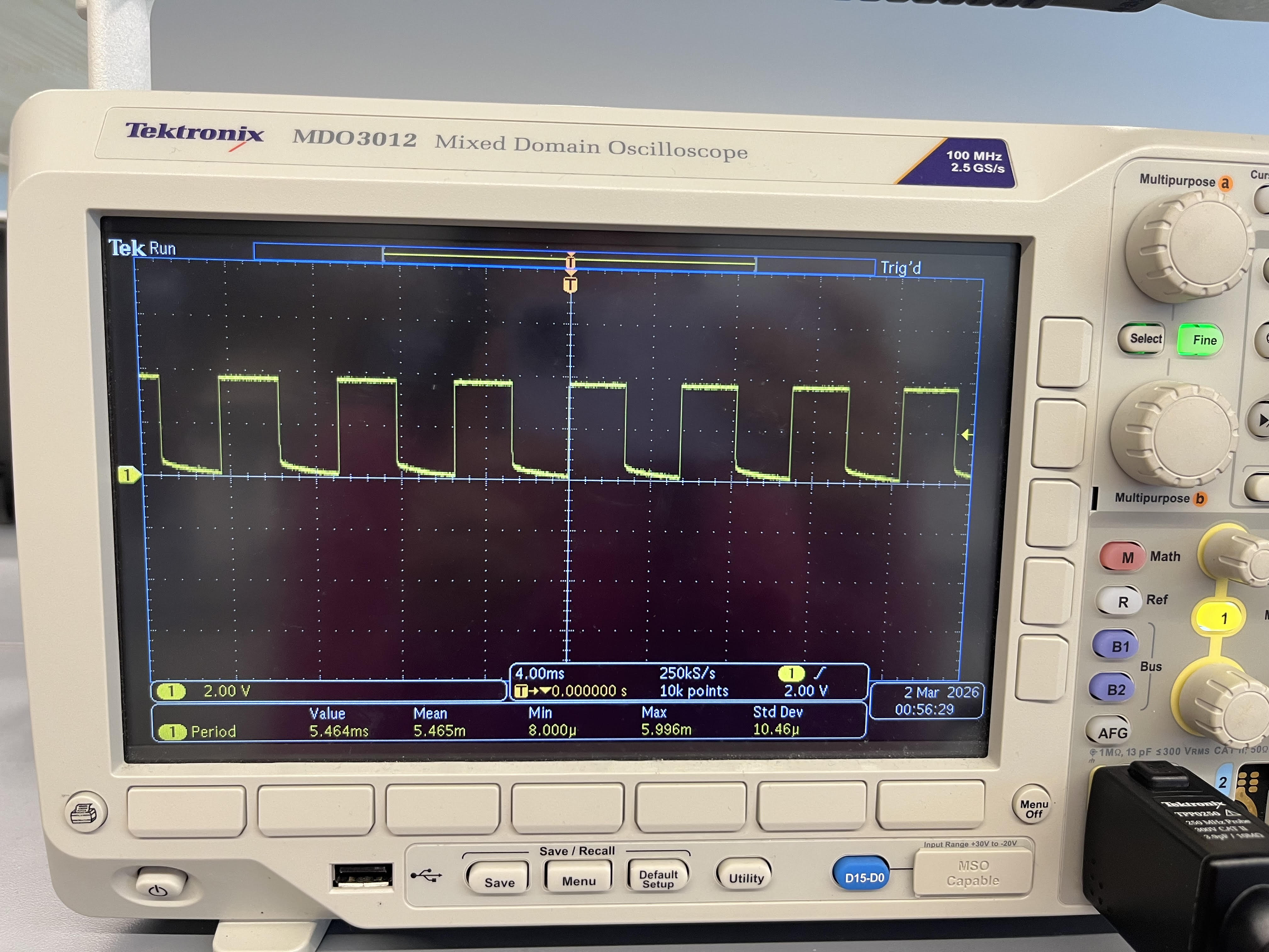
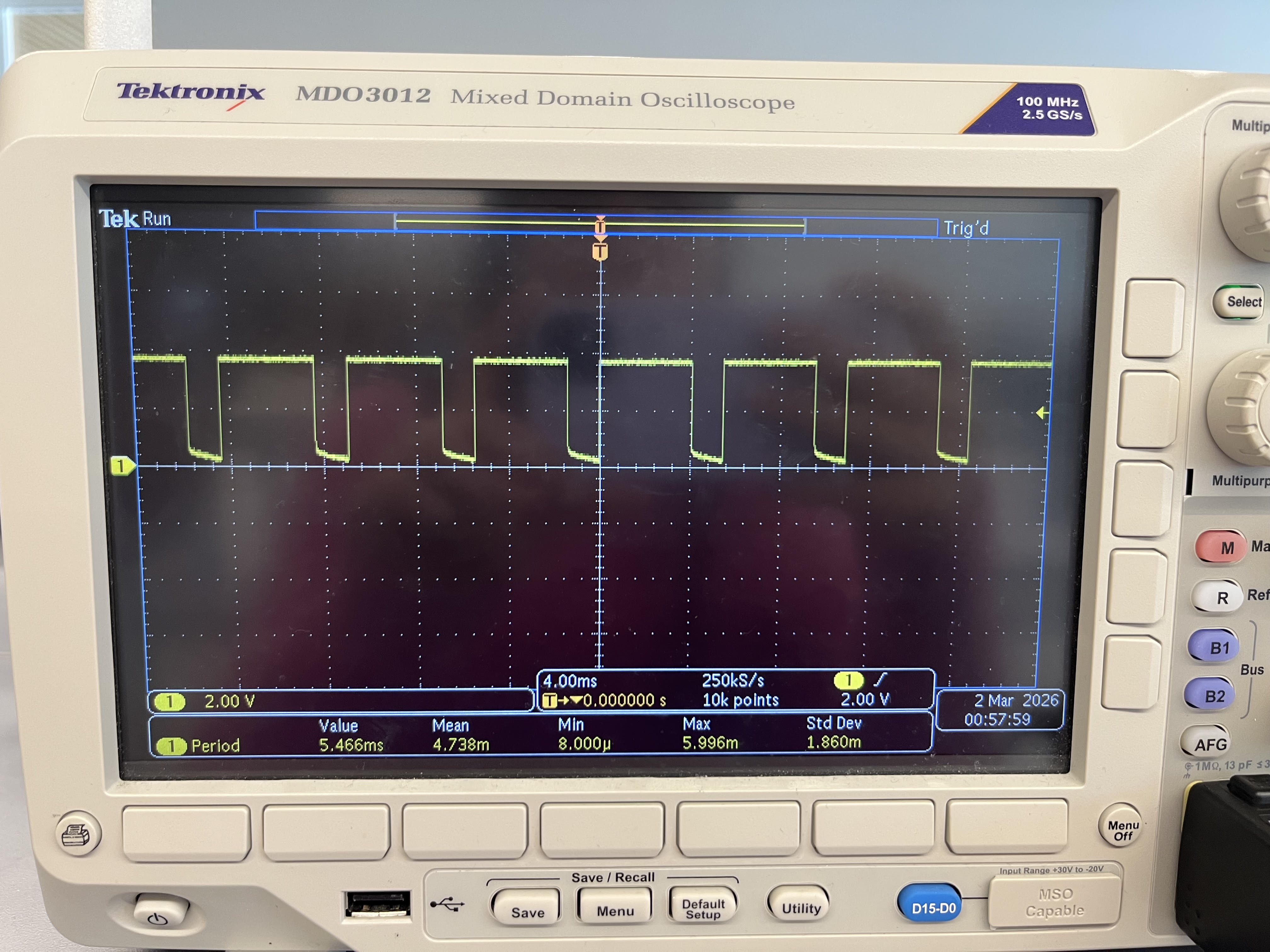
In order to measure the frequency that the analogWrite generates, I turn to the oscilloscope's output. The image shows that the signal has a period of about 5.464 ms, which equates to about 183 Hz. The frequency is the same for all duty cycles.
This frequency seems to be adequately fast, given that the motors were able to run well, however, if the frequency dips too low, then the current ripple in the signal increases, along with noise and vibration given the filtering nature of the motor. Manually configuring the timers to generate a faster PWM signal may eliminate these effects and provide a cleaner signal that would make the motors run more efficiently.
As previously shown, the lowest PWM value that the robot starts moving forward in a straight line is ~30. However, once it is running, the minimum PWM signal needed to do so is about ~35 for the right wheels and ~44 for the left wheels (given the motor calibration). Also it is important to note that this was run on vinyl (unleveled) floor, not the lab floor.
Additionally, the lowest PWM signal for the robot to perform a one-axis turn on from rest was found to be ~130, however, the minimum value for it to continue turning is about 135 and 169 for the right and left wheels respectively.
References
This lab required significant time in the lab for soldering, therefore for the majority of my questions I went to the TAs and Professor Farrell for help. Aside from this, I referened Aidan Derocher's course website from last year.