Lab 9
Prelab
The goal of this lab is to map out a room or series of objects using the robot's Time of Flight sensor. I decided to do this using PD control on orientation, merging all of the sensor readings using transformation matrices, and plot the results. I will later use these to draw the map using straight line segments.
Task 1
I decided to control my robot by repeatedly using PD control. On the Python side, I had the code loop through 14 steps of 25 degrees each, sending a new target angle after each step completed.
I start off by calling the SPIN case which initializes everything and takes in four values: proportional gain, derivative gain, motor calibration, and the target yaw angle:
 case SPIN:{
    float p_gain, d_gain, calibration, TARGET;

    success = robot_cmd.get_next_value(p_gain); if (!success)return;
    success = robot_cmd.get_next_value(d_gain); if (!success)return;
    success = robot_cmd.get_next_value(calibration);if (!success)return;
    success = robot_cmd.get_next_value(TARGET);if (!success)return;

    do {
        myICM.readDMPdataFromFIFO(&data);
    } while (myICM.status == ICM_20948_Stat_FIFOMoreDataAvail);
    if ((myICM.status == ICM_20948_Stat_Ok) && (data.header & DMP_header_bitmap_Quat6)) {
        double q1 = ((double)data.Quat6.Data.Q1) / 1073741824.0;
        double q2 = ((double)data.Quat6.Data.Q2) / 1073741824.0;
        double q3 = ((double)data.Quat6.Data.Q3) / 1073741824.0;
        double q0 = sqrt(1.0 - min(1.0, q1*q1 + q2*q2 + q3*q3));
        yaw_g = atan2(2.0*(q0*q3 + q1*q2), 1.0 - 2.0*(q2*q2 + q3*q3)) * 180.0 / M_PI;
    }
    prop_gain = p_gain;
    der_gain = d_gain;
    cal = calibration;
    target = TARGET;
    count = 0;
    prev_meas = yaw_g;
    prev_error = 0;
    last_pi_ms = millis();
    last_capture_index = -999;
    stopped = false;
    pi_spin = true;
    break;
}
The above case sets 'pi_spin = true', which triggers the PD_SPIN() function in the main loop which computed the error and calculated the necessary pwm:
float errorr = target - yaw_g;
while (errorr >  180.0f) errorr -= 360.0f;
while (errorr < -180.0f) errorr += 360.0f;
if (errorr > 0) errorr = errorr - 360.0f;  //<- forcing it to go CCW

float derivative = (errorr - prev_error)/dt;
prev_error = errorr;

pwm = (prop_gain * errorr) - (der_gain * derivative);
float pwm_range = constrain(abs(pwm), 60, 90);
I decided to force the robot to go CCW in some instances, such that it would take the long way and complete the entire circle.
Once the error drops within 1 degree of the target, the car stops and ouputs: "Within target range."
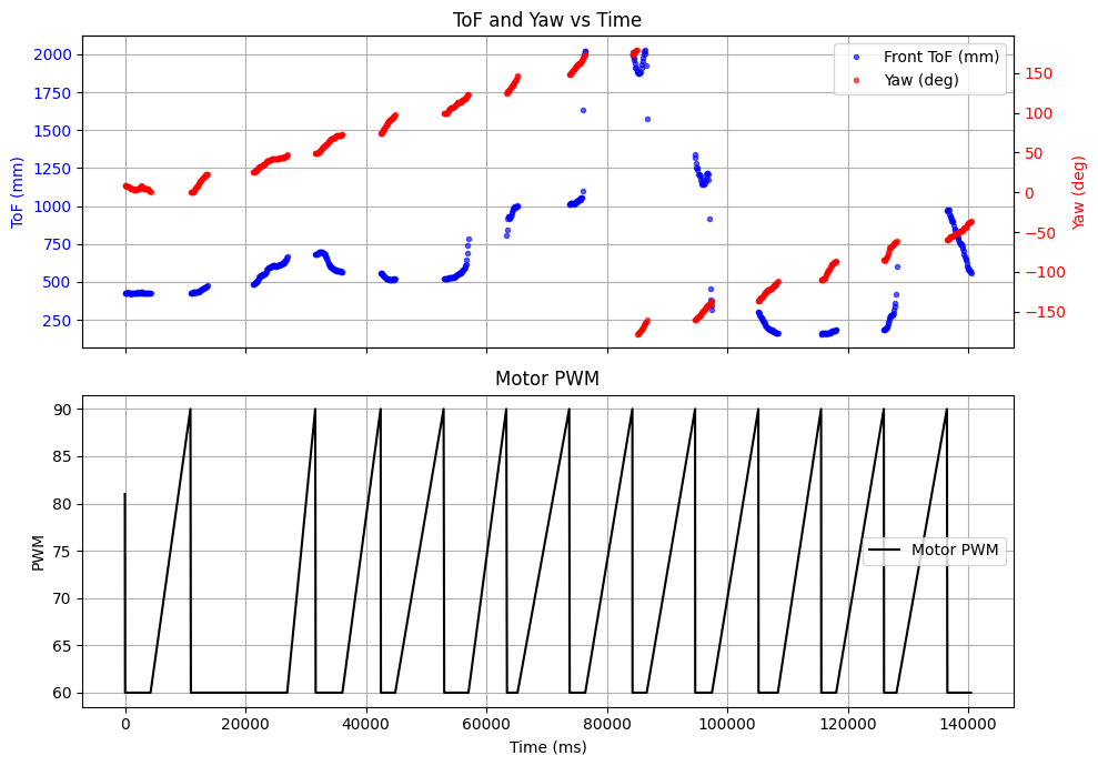
The robot paused between steps, which guarantees that the ToF sensor is pointing at a fixed point in space before logging data. My car was not perfect at completing on-axis turns due to motor asymmetry, which I corrected with a calibration factor applied to the left motor.
Here is a snippet from one of the runs:
Unfortunately I was unable to get my car to perfectly turn on-axis and there was an error of about 3 inches around the perimeter of an empty 4x4 meter room.
The plot below shows the yaw and ToF readings over time, and the motor PWM showing each of the 14 steps:
Task 2 — Read Out Distances
After each full 360° scan, the data was sent back over BLE using the SEND_DATA command and collected into a messages list. Each message contained the timestamp, ToF reading, yaw angle, and motor PWM. The polar plot below shows the scan:
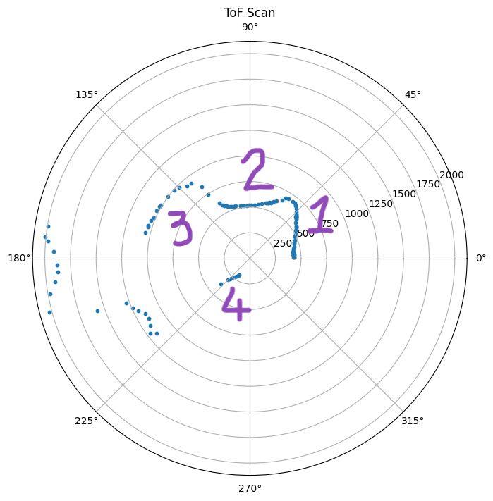
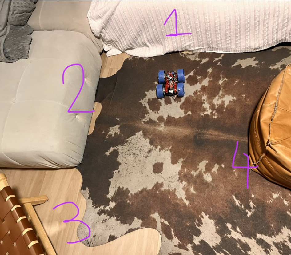
I did not have enough time to use the lab's map, so instead I mapped out the shown objects in a living space. The polar plot shows a reasonable scan of the environment.
Task 3 — Merge and Plot Readings
To convert the sensor readings from the robot's frame to the inertial world frame, I used transformation matrices. The robot is placed at a known position (x_0, y_0) in the room, and at each measurement the sensor is pointing at angle θ (the yaw reading). The ToF sensor is mounted at the front of the robot, offset from the center of rotation by a distance d along the robot's x-axis.
Task 4 - Taking Measurements from Mutiple Locations
The full transformation from sensor frame to world frame is:
$$ T_{world} = T_{robot in world} T_{sensor on robot} $$
Where
$$ T_{robot in world}= \left[\begin{matrix} cos(\theta) & -sin(\theta) & x_{0}\\ sin(\theta) & cos(\theta) & y_{0}\\ 0 & 0 & 1 \end{matrix}\right] $$
$$ T_{sensor on robot}= \left[\begin{matrix} TOF\\ 0 \\ 0 \end{matrix}\right] $$
My ToF front sensor is located about 2.5" in front of the center of the car.